How to Install & Remove the JF-1A Conductivity Sensor
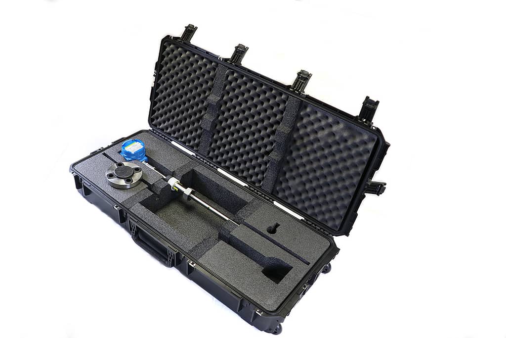
This is a quick guide showing our customers how to install and remove the JF-1A Conductivity Sensor in the field. This is the standard JF-1A as the high pressure sensor has a fixed flange. We designed the JF-1A to be able to be installed under full line pressure, and removed under the same conditions without any fuel spilling. For more information on the JF-1A Sensor click here
First you should refer to the JF-1A Installation & Safe Use Manual
Quick Guide:
How to Install:
- Add Never Seize grease packet to locking nut.
- Put sensor tip into ball valve connection point and screw onto the connection with the locking nut.
- Open Ball Valve and push sensor tip into the product line, ensuring fuel flow by the sensor tip.
- Hand tighten delrin locking nut into place to hold sensor at current depth into product line.
- Insert electrical connections into sensor head, and make conduit connections.
- Make the electrical connections and close up the sensor head.
- Check sensor output.
How to Remove:
- Disconnect Electrical Connections, ensuring they are isolated and do not touch.
- Remove any conduit connections.
- Loosen Locking Nut
- Pull Sensor Out of the Ball Valve, if sensor is stuck use a rubber mallet and tap lightly to get sensor moving.
- Close ball valve once sensor is completely out.
- Break seal with pipe wrench on locking nut and unscrew locking nut from ball valve connection point.
- Pull sensor out of the line.